

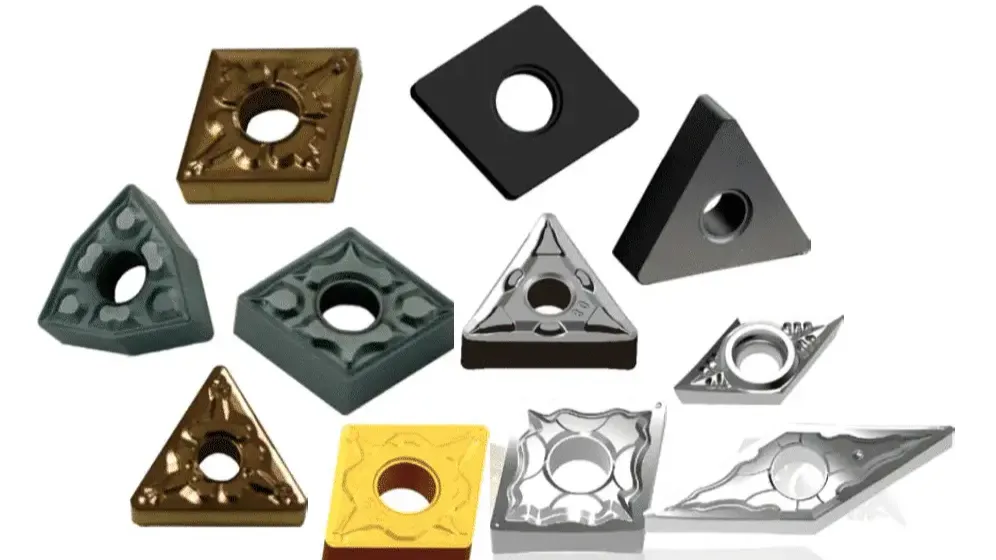
Buyers often copy a code from an old insert box, only to find that the replacement fits but performs poorly. Answering what carbide insert do I need starts with the operation, holder, workpiece material, and cutting conditions that the new edge must handle.
A practical order starts with project-based insert recommendations, followed by checks for grade and geometry and insert code compatibility. A CNMG may suit rigid steel turning, while a CCMT can reduce cutting force in boring. The chipbreaker must still match the planned feed and depth of cut.
Key Takeaways
- Holder Fit: Match the complete insert code to the pocket, clearance angle, size, thickness, and clamping method.
- Project First: Turning, boring, threading, grooving, and milling require different insert families and dedicated holder systems.
- Material Match: ISO P, M, K, N, S, and H grades cover different workpiece materials and wear conditions.
- Cutting Window: The chipbreaker must support the planned feed and depth of cut before you approve the order.
1. What Carbide Insert Do I Need for My Project?
Start with the machining operation and the tool that holds the insert. These two facts limit which insert family can perform the job. Workpiece material and cutting conditions then determine the grade, chipbreaker, edge preparation, and nose radius. SME treats shape, clearance angle, insert size, nose radius, and chipbreaker design as separate selection factors (Cutting Tool Geometries, SME).
- Identify the operation: external turning, facing, profiling, boring, grooving, parting, threading, or milling.
- Record the complete holder or cutter model. Check its pocket shape, insert size, clearance angle, and clamping method.
- Confirm the workpiece material and hardness. Place it in the correct ISO P, M, K, N, S, or H group.
- Define the cutting duty. Note whether the job involves finishing, medium machining, roughing, or interrupted cutting.
- Record the planned feed rate and depth of cut. The chipbreaker must operate within both ranges.
- Check machine power, tool overhang, workholding, and part rigidity.
- Set the required finish, tolerance, and smallest corner radius allowed by the drawing.
A similar-looking replacement can seat incorrectly or fail under the intended load. Check the full designation and the manufacturer’s application data before ordering. If the existing code is missing, send CarbideMatch the holder model, material, operation, and cutting parameters. Its application-matching process uses these details to identify suitable geometries and grades.
2. Project-Based Carbide Insert Recommendations
The families below provide a starting point. Final selection still depends on the tool pocket, work material, machine condition, and cut.
| Project | Common starting family | Geometry direction | Main buying check |
|---|---|---|---|
| General steel turning | CNMG or WNMG | Strong negative geometry | Holder code and ISO P grade |
| Heavy roughing | CNMG, SNMG, or round | Strong corner and tough edge | Machine power and interrupted entry |
| Fine profiling | CCMT, DCMT, or VBMT | Positive, lower-force geometry | Required profile and corner radius |
| Boring | CCMT or DCMT | Positive geometry | Boring-bar pocket and overhang |
| Stainless steel | Holder-compatible turning insert | Sharp geometry and ISO M grade | Chipbreaker feed range |
| Aluminum | Polished positive insert | Sharp, often uncoated edge | Pocket fit and adhesion risk |
| Grooving or parting | Holder-specific insert | Width and reach set by the job | Blade and pocket designation |
| Threading | Full- or partial-profile insert | Pitch-specific geometry | Thread standard and internal or external use |
| Milling | Cutter-specific insert | Geometry set by cutter body | Exact cutter model and insert seat |
The holder provides the final compatibility check. Two inserts can share a similar outline while using different clearance angles, thicknesses, holes, or clamping forms.
General Steel Turning and Facing
CNMG and WNMG are common choices for external turning on rigid machines. Both are usually negative inserts, so the holder creates the working clearance. Their supported edges suit medium cuts and roughing, although they produce more cutting force than positive inserts.
For carbon and alloy steel, begin with an ISO P grade and a chipbreaker made for the planned feed and depth of cut. For example, CNMG 120408 identifies an 80-degree rhombic insert with zero clearance, a 12.7 mm inscribed circle, 4.76 mm thickness, and a 0.8 mm corner radius. Its common ANSI equivalent is CNMG 432. Machining Doctor lists the same dimensions in its insert data table (Insert Data, Machining Doctor). CarbideMatch also lists CNMG inserts for application review.
Heavy Roughing and Interrupted Cuts
Heavy roughing needs enough carbide behind the cutting edge. CNMG and SNMG provide strong corners, while round inserts spread the load over a curved edge. These shapes withstand heavier loads but cannot reach every profile.
Interrupted entry adds impact at the edge. Choose a tougher grade and an edge treatment made for shock. A honed or chamfered edge can resist chipping better than a sharp finishing edge. The roughing chipbreaker must also work at the actual feed and depth of cut. Check machine power and setup stability before increasing the nose radius.
Fine Finishing and Profile Turning
Positive inserts reduce cutting force and reach features that broad negative inserts may miss. CCMT suits light turning and boring. DCMT reaches tighter shoulders, while VBMT is intended for fine profiles and narrow access.
| Insert family | Point angle | Edge strength | Access | Common use |
|---|---|---|---|---|
| CCMT | 80° | Higher | Moderate | Light turning and boring |
| DCMT | 55° | Medium | Good | Profiling and shoulders |
| VBMT | 35° | Lower | Very good | Fine profiles and narrow features |
Use the strongest shape that can produce the required profile. A small nose radius reduces radial force on slender work. A larger radius supports heavier feed on a stable setup, but excess radius can push a thin part away or cause chatter. CarbideMatch’s CCMT insert range provides an internal reference for positive turning inserts.
Boring, Thin Walls, and Small Lathes
Boring bars bend more easily than external toolholders. Use the largest bar diameter that fits the bore and keep the overhang short. Positive CCMT or DCMT inserts reduce cutting force, while a smaller nose radius can lower radial pressure on the bar or thin workpiece.
Small manual lathes may lack the speed or power needed for a large negative insert. A smaller positive insert often cuts more freely. HSS can suit machines that cannot reach a useful carbide cutting speed or jobs that need a custom edge.
Stainless Steel, Aluminum, and Cast Iron
These materials produce different wear and chip-control problems. Their grades and edge geometries should follow the workpiece material.
| Material | ISO group | Preferred edge | Grade or coating direction | Common problem |
|---|---|---|---|---|
| Stainless steel | M | Sharp, positive geometry | Tough grade, often PVD-coated | Work hardening and stringy chips |
| Aluminum | N | Polished, high-positive edge | Often uncoated carbide | Built-up edge |
| Cast iron | K | Stable, wear-resistant edge | Abrasion-resistant grade | Fast flank wear |
Stainless steel needs an edge that cuts without rubbing. Aluminum benefits from polished geometry that reduces material adhesion. Cast iron calls for wear resistance because its particles abrade the cutting edge. In each case, confirm that the chipbreaker operates at the programmed feed and depth of cut.
Grooving, Threading, Parting, and Milling
These jobs use dedicated insert systems. Selection begins with the holder or cutter body because its pocket controls the compatible shape and clamping form.
- Grooving inserts must match the holder, groove width, maximum depth, and corner form.
- Parting inserts must fit the blade and provide enough reach for the cutoff diameter.
- Threading inserts must match the thread standard, pitch, hand, and internal or external operation.
- Milling inserts must fit the cutter pocket, screw, approach angle, and seat.
16ER commonly identifies an external right-hand threading family, while 16IR is used for internal right-hand work. APKT and APMT are familiar milling families, but those letters alone do not confirm cutter compatibility. Send the complete cutter or holder code when requesting a substitute. CarbideMatch separates its catalog into dedicated turning, milling, threading, grooving, and parting categories.
3. Match the Grade and Geometry to the Material
The insert family determines the physical cutting form. Workpiece material then guides the carbide grade, coating, edge preparation, and chipbreaker. Seco Tools divides common workpiece materials into P, M, K, N, S, and H groups (ISO Standards in Tooling, Seco Tools). Manufacturers still use their own commercial grade names within those groups.
| ISO group | Workpiece material | Cutting behavior | Selection priority |
|---|---|---|---|
| P | Carbon and alloy steel | Heat and crater wear during longer cuts | Balance wear resistance and toughness |
| M | Stainless steel | Work hardening and adhesion | Sharp edge, toughness, chip control |
| K | Gray and ductile iron | Abrasive wear and short chips | Edge stability and wear resistance |
| N | Aluminum and nonferrous metals | Adhesion and built-up edge | Polished, sharp geometry |
| S | Titanium and heat-resistant alloys | Heat remains near the cutting edge | Tough edge and heat control |
| H | Hardened steel | High edge stress and temperature | Hard-turning grade or CBN where suitable |
Harder grades can give longer wear life during stable, continuous cuts. Tougher grades usually handle impact or interrupted entry better. CVD coatings are commonly used for heat and wear resistance in stable steel or cast-iron turning. PVD coatings can retain a sharper edge for stainless steel, finishing, and less stable cuts. Uncoated carbide is common for polished aluminum inserts. Cermet, ceramic, CBN, and PCD cover narrower applications and require matching holders and cutting conditions.
4. Read the Insert Code and Avoid a Bad Purchase
MachRef explains how a code such as CNMG 120408 identifies shape, clearance, tolerance, configuration, size, thickness, and corner radius (Indexable Insert Identification, MachRef). Later suffixes often identify a manufacturer’s chipbreaker and grade. Those suffixes are not shared standards and must be checked in the relevant catalog.
| Code or symptom | Meaning or likely cause | Buying or process check |
|---|---|---|
| C | 80-degree rhombic shape | Holder must accept a C-shaped insert |
| N | Zero-degree clearance | Requires a negative-geometry holder |
| M | Insert tolerance class | Check repeatability requirements |
| G | Hole and chipbreaker configuration | Confirm clamp and pocket design |
| 12 | 12.7 mm inscribed-circle family | Match the pocket size |
| 04 | 4.76 mm thickness | Match pocket depth and support |
| 08 | 0.8 mm corner radius | Check finish, cutting force, and part radius |
| Long chips | Feed or depth may miss the chipbreaker range | Check the published operating chart |
| Fast chipping | Grade or edge may be too brittle | Check impact, seating, and grade toughness |
| Built-up edge | Material is sticking to the edge | Check speed, sharpness, and coating |
| Chatter | Force or overhang may be excessive | Shorten overhang or reconsider nose radius |
| Fast flank wear | Speed or grade may be unsuitable | Check cutting speed and wear resistance |
| Poor finish | Wear, feed, chatter, or adhesion may be present | Inspect the edge before changing grades |
A purchase request should include the current insert code, holder or cutter designation, material and hardness, operation, feed, depth of cut, finish target, quantity, and delivery country. Describe the current problem and attach a clear photo when identification is uncertain. A substitute may share the base ISO dimensions while using a different substrate, coating, edge treatment, or chipbreaker range. Buyers can review the CarbideMatch insert catalog or submit the application for matching.
5. Frequently Asked Questions
Is CNMG the Best General-Purpose Carbide Insert?
CNMG is a common choice for external turning and facing on rigid machines. Its 80-degree corner provides good strength, and a double-sided insert can provide four usable cutting edges.
Low-power machines, thin walls, small bores, and tight profiles may run better with a positive CCMT, DCMT, or VBMT insert.
What Carbide Insert Should I Use for Mild Steel?
Start with an ISO P grade in the shape and size required by the holder. Match the chipbreaker to roughing, medium turning, or finishing, then confirm its feed and depth-of-cut range. CNMG and WNMG suit many rigid external-turning jobs, while CCMT or DCMT can reduce force on lighter setups.
What Insert Works Best for Stainless Steel?
Use an ISO M grade with a sharp geometry and a chipbreaker made for stainless steel. The insert family must still match the holder and operation.
Keep the feed high enough for the edge to cut and for the chipbreaker to work. Rubbing can harden the surface, while uncontrolled chips can wrap around the tool or part.
Should I Choose a Positive or Negative Insert?
Choose a positive insert when low cutting force matters. Choose a negative insert when the machine and setup can support a stronger, higher-force edge.
| Positive insert | Negative insert |
|---|---|
| Suits lower-power machines | Suits rigid, higher-power machines |
| Useful for thin or slender parts | Useful for external turning and roughing |
| Common for boring and light finishing | Often provides more usable edges |
| Usually single-sided | Often double-sided |
What Nose Radius Should I Use?
Use a smaller nose radius for light finishing, thin walls, slender shafts, and tight features. It lowers radial force but provides less support behind the edge.
Use a larger radius for heavier feed on a stable setup. Check the drawing because the insert cannot produce a corner smaller than its radius. Too much radius can also cause chatter.
Can I Use the Same Insert for Roughing and Finishing?
A medium-duty geometry can cover both operations when the cuts stay within its feed and depth ranges. Separate inserts are safer when chip control, finish, cycle time, or edge life has a large effect on part cost.
How Do I Know Whether an Insert Fits My Toolholder?
Compare the complete holder and insert designations. A matching shape alone does not confirm fit.
- Match the insert shape.
- Match the clearance angle.
- Confirm the inscribed-circle size.
- Confirm the insert thickness.
- Check the hole and clamping form.
- Check hand and approach direction where applicable.
- Verify the combination in the holder manufacturer’s catalog.
6. Conclusion
Choosing an insert becomes easier when the project sets the order. The operation identifies the insert family, the holder limits the shape and size, and the material guides the grade. Feed, depth of cut, rigidity, and finish then narrow the choice. If you began by asking what carbide insert do I need, you can now prepare a specification instead of relying on appearance or a partial code.
Send CarbideMatch your insert or holder code, workpiece material, operation, cutting parameters, tooling problem, and quantity. You will receive an application review that can support product matching, availability checks, samples, and a quotation.