

A buyer can match an insert’s shape and size yet still choose the wrong cutting geometry. The missing detail is often flank clearance. If the insert rubs the machined surface or lacks enough edge support, tool life and finish can suffer even when the grade is correct.
The answer starts with reading the clearance code, then checking how the holder changes the angle in the cut. Comparing positive and negative inserts and recognizing wrong clearance symptoms helps you choose between common 0, 7, and 11 degree designs without treating a larger angle as automatically better.
Key Takeaways
- Clearance Purpose: The angle keeps the insert flank away from the machined surface so the cutting edge can work.
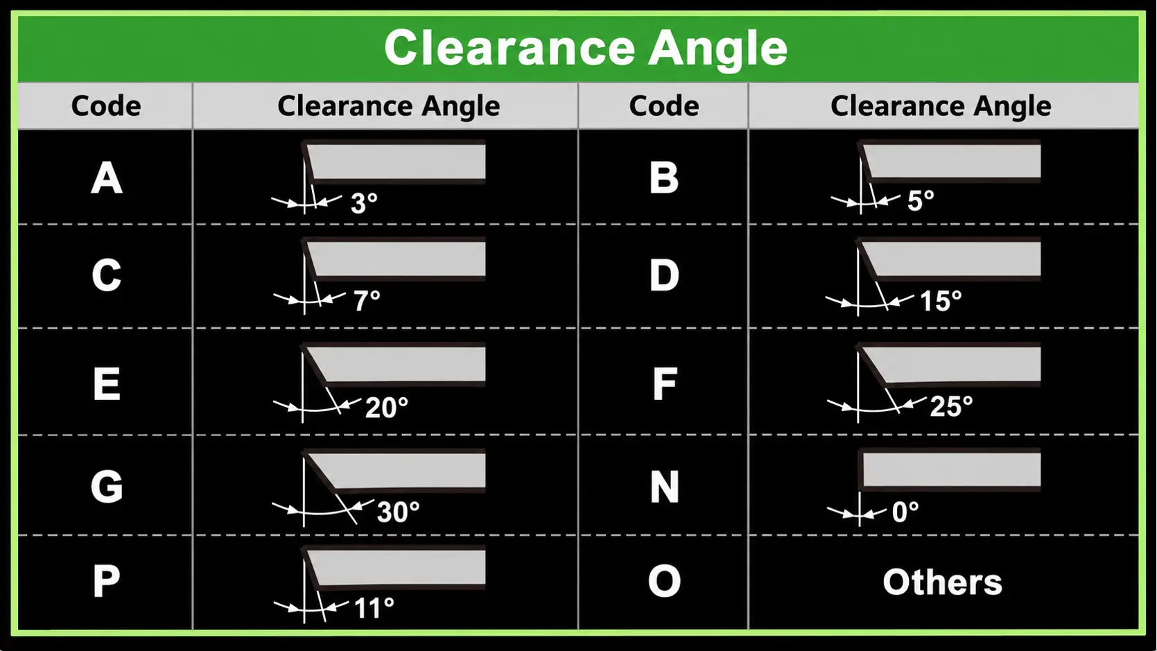
- Code Position: The second letter in an ISO turning insert designation identifies the insert’s nominal normal clearance angle.
- Holder Effect: Pocket tilt, tool height, feed direction, and workpiece geometry can change clearance where cutting actually occurs.
- Balanced Choice: More clearance reduces rubbing, but it also removes support behind the edge and can increase chipping risk.
What Is the Clearance Angle of an Insert?
The clearance angle of an insert is the angle that prevents the flank, or side below the cutting edge, from rubbing against the newly machined surface. Mitsubishi Materials defines the flank angle as the angle between the machined surface and the insert’s flank face (Insert Terminology, Mitsubishi Materials). Without enough clearance, the flank can contact the part instead of leaving space behind the active cutting edge.
The value in an insert code is its nominal normal clearance, not a complete description of the cutting geometry at the machine. Rake angle describes the chip-flow side of the cutting edge. Wedge angle describes the material supporting that edge. The holder pocket can tilt the insert and change its working rake and clearance. Tool height, feed direction, workpiece diameter, and a thread’s helix angle can also change the effective clearance during the cut.
How to Read the Clearance Angle in an Insert Code
ISO 1832 places the normal clearance symbol in the second position of a standard insert designation. In CNMG, the N is the clearance code. In CCMT, the second C is the clearance code, while the first C identifies the 80 degree rhombic shape. The remaining characters describe tolerance, insert type, size, thickness, corner radius, and optional features.
| Second letter | Nominal clearance | Common description |
|---|---|---|
| N | 0° | Negative insert |
| A | 3° | Positive insert |
| B | 5° | Positive insert |
| C | 7° | Positive insert |
| P | 11° | Positive insert |
| D | 15° | Positive insert |
| E | 20° | Positive insert |
| F | 25° | Positive insert |
| G | 30° | Positive insert |
| O | Special | Requires a more specific description |
Walter’s ISO 1832 designation key and Mitsubishi’s turning identification guide use this second-letter system (Designation Key for Indexable Turning Inserts, Walter Tools; Insert Turning Identification Code, Mitsubishi Materials). The code does not specify the carbide grade or the manufacturer’s chipbreaker design. Use the complete insert designation and grade when checking a replacement through an insert supplier.
What Changes Between Positive and Negative Inserts?
Positive and negative describe the insert’s cross-sectional form. A positive insert has an inclined side that creates a built-in clearance angle. A negative insert has parallel sides and a nominal 0 degree clearance. The holder must tilt a negative insert to create the working clearance required at the part.
| Selection factor | Positive insert | Negative insert |
|---|---|---|
| Nominal clearance | Greater than 0° | 0° |
| Cross section | Side slopes inward | Side is generally perpendicular to top and bottom |
| Edge support | Thinner cutting wedge | Thicker, stronger cutting wedge |
| Usable sides | Commonly one-sided | Often usable on both sides |
| Cutting force | Often lower with a sharp positive geometry | Often higher, depending on chipbreaker and holder geometry |
| Typical fit | Finishing, profiling, small bores, thin parts, lighter machines | Stable roughing, stronger setups, and applications valuing edge economy |
| Main tradeoff | Easier cutting with fewer usable edges | Stronger edge and more edge economy with higher force potential |
ISCAR explains that negative inserts can provide cutting edges on both top and bottom, while positive shapes give designers more freedom to create positive working rake angles (Cutting Tools User Guide, ISCAR). A negative insert can still use a chipbreaker with positive rake at the cutting zone. Therefore, negative insert does not mean every angle in the assembled tool is negative.
How to Choose the Right Clearance Angle for the Application
Start with the holder rather than selecting an angle in isolation. The pocket, clamp, insert thickness, and cutting-edge position determine which insert family will seat correctly. After confirming compatibility, choose enough effective clearance to avoid flank contact while keeping adequate material behind the edge.
- Read the holder code and manufacturer data to identify the required insert shape and clearance class.
- Define the operation, including external turning, facing, boring, profiling, or milling.
- Check whether the cutter must enter a small bore, follow a tight contour, or work close to a shoulder.
- Consider workpiece rigidity, wall thickness, machine stability, and tool overhang.
- Estimate whether the material and cutting conditions are likely to create flank rubbing or high cutting force.
- Balance finish and force requirements against the edge strength needed for feed and depth of cut.
- Run a controlled trial and inspect the flank, cutting edge, part finish, dimensions, heat, and vibration.
Shop-floor experience shows why this decision stays application-specific. In a Practical Machinist discussion, one user favored 11 degree TPMT or TPGT inserts for aluminum, plastics, finish turning, and boring on a smaller machine, while still recognizing the edge-strength limit in heavier steel roughing. Other machinists emphasized contour clearance, small-bore access, and the effect of holder-pocket geometry (Insert Clearance Angles. Uses?, Practical Machinist). These are field observations, not a universal rule for every holder or material.
What Happens When the Clearance Angle Is Wrong?
The best clearance angle is large enough to prevent the flank from contacting the work and no larger than the edge can support. A problem may come from the nominal insert angle, but it may also come from an incompatible pocket, incorrect center height, long overhang, workpiece geometry, or the direction of feed.
| Symptom | Possible clearance-related cause | What to check |
|---|---|---|
| Polished flank immediately below the edge | Too little effective clearance | Insert code, holder tilt, center height, bore diameter, and feed direction |
| Heat without expected chip load | Flank rubbing on the workpiece | Clearance at the actual contact point and material springback |
| Chatter during a light finishing pass | Rubbing, weak setup, or unsuitable edge geometry | Tool height, overhang, insert sharpness, holder, and cutting data |
| Poor surface finish | Flank contact, vibration, built-up edge, or damaged edge | Wear pattern, finish direction, speed, feed, and workholding |
| Early edge chipping | Excessive clearance or insufficient wedge support | Nominal angle, pocket tilt, edge preparation, feed, and interrupted cuts |
| Trouble profiling near a wall | Insert body or flank lacks physical space | Insert shape, relief, approach direction, and wall geometry |
| Rubbing in a small bore | Effective clearance falls as the geometry tightens | Bore diameter, insert size, holder design, and center height |
The forum discussion offers a useful shop rule: use enough effective clearance to stop contact, rather than choosing the largest nominal angle available. Participants also warned that a 7 degree insert may not seat or receive proper support in a pocket designed for an 11 degree insert. For thread turning, ISCAR notes that the insert inclination must account for the thread helix so both flanks receive suitable clearance (Flank Clearance and Effective Inclination Angle, ISCAR). Diagnose the assembled tool before blaming the insert alone.
Frequently Asked Questions
Is Clearance Angle the Same as Rake Angle?
No. Clearance angle creates space between the insert flank and the machined surface. Rake angle describes the orientation of the surface over which the chip flows. Both affect the wedge supporting the cutting edge, but they describe different parts of the geometry.
What Does the N Mean in a CNMG Insert?
The N in the second position of CNMG means the insert has a nominal 0 degree clearance angle. It is classified as a negative insert. The first C identifies the 80 degree rhombic shape.
What Is the Clearance Angle of a CCMT Insert?
The second letter C in CCMT represents a nominal 7 degree clearance angle. This is the insert’s standardized normal clearance. The holder and cutting setup determine the effective angle at the workpiece.
Should I Choose a 7° or 11° Clearance Insert?
A 7 degree insert usually retains more material behind the cutting edge, while an 11 degree insert provides more flank clearance. The extra relief can help in finishing, profiling, small bores, or low-force applications, but the thinner wedge has less support.
Choose only after confirming the holder pocket. A 7 degree and an 11 degree insert are not interchangeable simply because their top-view shape and nominal size look similar. Compare wear and finish in a controlled trial.
Why Do Positive Inserts Usually Have Fewer Usable Edges?
The sloped side that creates built-in clearance normally makes the insert one-sided. A negative insert has parallel sides and can often carry usable cutting edges on both faces, which increases edge economy when the holder and operation support it.
Can the Toolholder Change the Effective Clearance Angle?
Yes. Pocket tilt and insert orientation change the angle at which the flank approaches the work. Tool height, feed direction, workpiece diameter, and special conditions such as a thread helix can change the effective clearance further.
Can I Replace a Negative Insert With a Positive Insert?
Not from size alone. The shape, clearance class, thickness, hole, clamp, pocket support, and cutting-edge location must match the holder. Check the complete holder and insert codes before making a substitution.
Conclusion
You now know what the clearance angle of an insert is and why the coded value is only the starting point. The right choice prevents flank rubbing while preserving enough support behind the edge. Check the insert code, holder pocket, effective cutting geometry, machine stability, and operation before choosing 0, 7, or 11 degrees.
If the holder and insert combination is unclear, send CarbideMatch both codes, the workpiece material, operation, cutting data, and wear photos. You can request a compatibility review, suitable geometry options, sample availability, and quotation details before changing a production setup.