

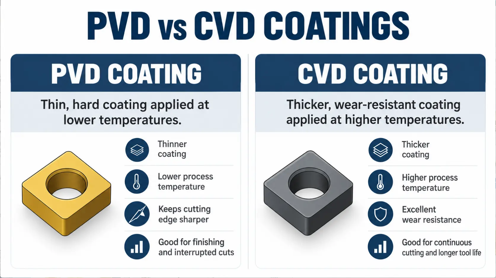
Buying a coated carbide insert by color or grade family alone can put the wrong edge into the cut. CVD and PVD create different coating thicknesses and stress states, so the better choice depends on cutting heat, contact time, and edge load.
CVD usually favors wear resistance during stable, hot cutting. PVD usually preserves a sharper, tougher edge when engagement changes. Understanding cutting performance, matching the coating to the machining operation, and checking the complete grade design helps buyers avoid a costly substitution based on one catalog label.
Key Takeaways
- Two Main Methods: CVD uses high temperature chemical reactions, while PVD deposits vaporized material at a lower process temperature.
- CVD Starting Point: Thicker CVD coatings usually suit stable, continuous cuts where heat and abrasive wear drive insert failure.
- PVD Starting Point: Thinner PVD coatings preserve sharp edges and commonly suit interrupted cuts, milling, threading, or unstable setups.
- Grade Still Matters: Substrate, coating material, edge preparation, chipbreaker, and cutting conditions can outweigh the deposition method alone.
What Are the Two Main Coating Methods on Carbide Inserts?
The two main coating methods are chemical vapor deposition, called CVD, and physical vapor deposition, called PVD. CVD forms a coating through chemical reactions between heated reactive gases and the carbide surface. PVD vaporizes or ionizes solid coating material in a vacuum and condenses it onto the insert. Both methods place a hard film over the carbide substrate, but they build that film under different conditions. Sumitomo Electric describes thermal CVD for carbide inserts as a process close to 1000°C, while its PVD range is below 600°C (Evolutional History of Coating Technologies for Cemented Carbide Inserts, Sumitomo Electric).
That temperature difference affects the finished edge. Sumitomo lists typical CVD thickness at 5 to 20 μm and PVD thickness at 0.5 to 5 μm. Its comparison also associates CVD with tensile residual stress and PVD with compressive residual stress. CVD therefore has a common role in stable turning where a thicker thermal and wear barrier helps. PVD is a common fit for interrupted cuts and tools that need a sharper edge. These are selection tendencies, not universal grade rules. The coating process is only one part of the carbide grade available through an insert selection.
How CVD and PVD Change Cutting Performance
The deposition method changes coating thickness, stress, edge condition, and the range of coating materials a manufacturer can apply. A thicker CVD stack can carry an alumina layer that limits heat reaching the substrate during long engagement. A thinner PVD layer follows a sharp edge more closely and its compressive stress can help the edge resist chipping. The substrate, coating stack, edge preparation, and post treatment still work as one system.
| Cutting factor | CVD coated insert | PVD coated insert | Practical effect |
|---|---|---|---|
| Typical process temperature | About 800°C to 1000°C | About 400°C to 600°C | PVD exposes the substrate to less coating heat |
| Typical film thickness | About 5 to 20 μm | About 0.5 to 5 μm | CVD supports a thicker barrier; PVD follows a sharp edge more closely |
| Residual stress tendency | Tensile | Compressive | PVD commonly supports better edge toughness |
| Common coating materials | TiC, TiN, TiCN, and Al2O3 | TiN, TiCN, TiAlN, TiSiN, and CrN | Available coating chemistry depends partly on the process |
| Edge condition | Usually prepared with a stronger hone | Can retain a finer, sharper edge | PVD often reduces cutting force in light or finishing cuts |
| Common cutting pattern | Stable, continuous engagement | Interrupted or changing engagement | Entry, exit, and impact frequency affect the choice |
| Typical wear target | Heat, crater wear, and abrasive wear | Edge chipping, adhesion, and unstable loading | Choose from the actual failure mode rather than the coating label |
The numerical ranges above describe typical process families, not every commercial grade. ISCAR places CVD near 900°C to 1000°C and describes the PVD temperature as roughly half the CVD level. It also notes that CVD forms a relatively thick coating for wear resistance and high temperature strength, while thinner PVD coatings suit sharp cutting edges (Cutting Tools User Guide, ISCAR). Modern manufacturers also control substrate composition, coating stress, surface smoothness, and edge honing, so an updated CVD grade may perform differently from an older grade carrying the same process label.
How to Choose CVD vs. PVD Carbide Inserts
Start with the operation and the failure you need to correct. Stable engagement at higher heat usually moves the first trial toward CVD. Frequent entry and exit, vibration, or a low cutting force requirement usually moves it toward PVD. Workpiece material matters, but the same material can need a different coating method when the cut changes from continuous roughing to light finishing.
| Operation or condition | Usual starting point | Why | Check before ordering |
|---|---|---|---|
| Continuous steel turning | CVD | Thick multilayer coatings can resist heat and crater wear during long engagement | Cutting speed, feed, depth, and current wear pattern |
| Stable cast iron roughing | CVD | Wear resistance and coating thickness suit abrasive, continuous cutting | Grade toughness and whether the cut includes scale or interruption |
| Stainless steel finishing | PVD | A sharper edge can reduce cutting force and limit material smearing | Edge preparation, chip control, and built up edge |
| Interrupted turning | PVD | Thin coating and compressive stress commonly support edge toughness | Interruption severity, impact, and holder rigidity |
| Indexable milling | PVD in many unstable or light applications | Repeated entry and exit load the cutting edge mechanically | Cutter pitch, runout, engagement, and machine stability |
| Threading or grooving | PVD | Thin coating preserves a precise, sharp profile | Insert geometry, overhang, coolant, and pass strategy |
| Stable high heat finishing | Application dependent | Thin CVD and specialized PVD grades can overlap | Manufacturer speed range and the complete grade recommendation |
Seco describes a milling grade as the combination of its base material, coating, and pre or post treatments. Its guidance lists CVD layers at 7 μm or thicker and PVD layers up to about 4 or 5 μm, while favoring PVD for sharp geometries (How to Select the Proper Milling Grade, Seco Tools). These ranges reinforce a starting point, not an automatic substitute. Match the exact insert geometry, chipbreaker, and holder. Then compare the supplier’s recommended ISO material group, cutting range, and stability class before approving a production quantity.
Why the Coating Method Is Only Part of the Grade Decision
Two CVD grades can behave differently because their substrates, layer materials, thicknesses, edge hones, and surface treatments differ. The same applies to PVD grades. A grade built on a hard substrate for stable finishing does not carry the same impact margin as one built on a tougher substrate, even if both use PVD. Purchasing by deposition method alone leaves out the features that control chip formation and edge survival.
- Verify the complete manufacturer grade, not only a CVD or PVD description.
- Check how the carbide substrate balances wear resistance against resistance to chipping.
- Confirm the coating materials and whether the supplier describes a single or multilayer design.
- Match the edge hone or sharp edge to feed, stability, and surface finish requirements.
- Keep the chipbreaker suited to the operation, feed range, and depth of cut.
- Confirm the manufacturer’s recommended ISO material family and hardness range.
- Review speed, feed, depth, coolant method, engagement, and current failure mode.
American Machinist notes that coating materials and layer thicknesses are selected around the intended application, and that thicker coatings become more sensitive to mechanical variation. The same article describes PVD as suitable for positive, sharper tools and CVD as better able to handle heat and longer engagement (The Development of Coated Grades of Carbide Tools, American Machinist). For a replacement review, send the full insert and holder codes, workpiece material, operation, cutting data, coolant method, failure photos, and required quantity through the CarbideMatch contact page.
Frequently Asked Questions
Is CVD Harder Than PVD?
Not by definition. CVD and PVD describe deposition methods, while hardness depends on the coating material, structure, layer design, and test conditions. A CVD alumina or TiCN stack and a PVD TiAlN layer cannot be ranked from the process name alone. Compare the actual grade data and intended wear mechanism.
Are CVD Coatings Always Thicker Than PVD Coatings?
CVD coatings are typically thicker in carbide cutting tools, but “always” is too absolute for commercial grades. Sumitomo lists typical CVD thickness at 5 to 20 μm and PVD at 0.5 to 5 μm (Evolutional History of Coating Technologies for Cemented Carbide Inserts, Sumitomo Electric). Specialized processes and grade designs can narrow the difference.
Which Coating Method Is Better for Interrupted Cuts?
PVD is usually the better starting point. Its thinner film preserves a sharper edge, and its compressive residual stress commonly supports chipping resistance during repeated entry and exit. Severe interruption still requires a suitable substrate, edge hone, geometry, and stable holder. The PVD label alone does not guarantee survival.
Is CVD or PVD Better for Turning Steel?
CVD commonly suits stable, continuous steel turning where heat and crater wear control tool life. PVD can be the better choice for light finishing, interrupted surfaces, slender parts, or setups that need lower cutting force. Use the operation and current failure mode to choose the first trial, then follow the grade maker’s cutting data.
Can Coating Color Identify CVD or PVD?
No. Color can suggest a surface material such as TiN, but it does not reliably identify the deposition method or the complete coating stack. Manufacturers may also apply post treatments that change the appearance. Read the laser grade mark and verify it in the correct manufacturer’s catalog.
What Information Is Needed to Replace a Coated Insert?
Provide the complete markings from the insert and package before selecting a replacement.
- Insert grade, geometry, and chipbreaker
- Holder or cutter code
- Workpiece material and hardness
- Turning, milling, grooving, or threading operation
- Cutting speed, feed, and depth of cut
- Coolant method, engagement, and setup stability
- Wear or failure photos and required quantity
This information lets a supplier review coating method, substrate, edge preparation, compatibility, availability, sample options, and quotation details as one decision.
Conclusion
Knowing what the difference between positive and negative turning inserts is helps you avoid ordering tools that will not fit your pockets. Negative inserts give you a strong 90 degree edge and double sided economy when your machine and setup are rigid. Positive inserts provide built in clearance that cuts freely and prevents chatter on boring bars, thin walls, and slender shafts. Your final choice always comes down to matching the insert relief angle to your holder style and part rigidity.
Send CarbideMatch your insert grade, holder code, workpiece material, hardness, operation, cutting data, coolant method, failure photos, and required quantity. You can request a review of coating fit, tool compatibility, availability, sample options, and quotation details before replacing a proven grade or committing to a production quantity.